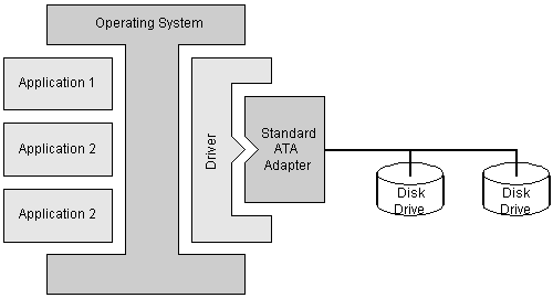
ATA INTERFACE
The ATA interface as defined in ATA-6 describes the physical, electrical, timing, protocol and command standards required to transfer data to and from a compliant device. That standard makes certain requirements on the Host adaptor but does not define any standards for the Host. This standard defines the register and physical requirements of Host adaptors. The objective is to enable Host software device drivers to be developed that can work with a Host adaptor supplied from a variety of vendors.
Host adaptors act as a bridge between the Host computers data bus and the ATA bus. Thus Host adaptors are required to meet at least two sets of standards. Host software device drivers have to be able to configure the adaptor for both the Host bus operation and the ATA bus operation. Thus this standard defines, where possible, a common API (Applications Programming Interface) for those functions.
Standard ATA device connectivity

Features:
- Adaptor Types: The ATA interface has evolved from an original plug in Host adaptor on the IBM PC-AT. This adaptor controlled hard drives that interfaced to it using an ST506 interface. ATA drives moved the functionality of that adaptor from a plug in card into the device. The same register set was retained and thus the most important attribute of the ATA interface was initiated, backward compatibility. Software drivers and BIOS code did not have to change.
- The first ATA Host adaptors were address decoder cards plugged into the ISA bus. The cards decoded the I/O addresses of the registers in the ATA register set and connected the ISA bus to the ATA bus. All timings on the ATA bus were those of the ISA bus. As time has progressed the performance of the ATA devices have far exceeded the capabilities of the ISA bus. The majority of Host adaptors now reside on the PCI bus and the Host adaptors have become more complex involving timing and protocol conversions as a very minimum.
- Legacy Mode: An adaptor is in Legacy Mode when the control of the transfer is through the ATA Command and Control Block Registers. Any data transfers are via PIO mode through the Data register. The addresses of the Command or Control block are configurable in this mode.
- Compatibility Mode:This mode is only applicable to implementations on PC systems implementing the PC architecture. An adaptor is in Compatibility Mode when the control of the transfer is through the ATA Command and Control Block Registers and registers in the adaptor. The addresses of the Command or Control block are defined as well as the host's interrupt lines (IRQs).
Table 1 defines the four standard I/O address banks.
Table 1 Compatibility Mode Standard I/O Register Addresses
| Channel | Command Block Registers | Control Block Register | IRQ | Alternate IRQ |
|---|
| Primary | IF0h-1F7h | 3F6h* | 14 | None |
| Secondary | 170h-177h | 376h* | 15 | None |
| Tertiary | 1E8h-1Efh | 3Eeh* | 11 | 12 or 9 |
| Quaternary | 168h-16Fh | 36Eh* | 10 | 12 or 9 |
| *NOTE - The control Block registers were originally defined to include a second register at 3F7h and 377h. This register address was shared with the Floppy Disk adaptor on the AT architecture. The floppy drive uses a 7 bit register; the device used 0-6. This register is no longer used in ATA standards |
- PCI-Native Mode :This mode is only applicable to adaptors bridging to the PCI bus. In this mode the control of the transfer is through the ATA Command and Control Block Registers and registers in the adaptor. The addresses of the Command or Control block are defined in the Base Address Register (BAR) of the adaptor and are defined by the Host software. There is only one Host interrupt line for all the channels attached to an adaptor.
- ADMA Mode: In this mode the ATA Command and Control Block registers are not accessible to the Host. Control is exercised through a data structure held in memory and adaptor registers.
BACK


